
Clear object detection using photoelectric sensors

Jeffrey R. Holman, Rockwell Automation Presence Sensing Business
The first technology developed to sense clear or translucent materials was used in capacitive proximity sensors. However, capacitive sensors were unable to completely satisfy the needs of customers due to the inherent limitations of the technology such as limited range (2mm-10mm) and sensitivity to moisture. The need to increase the sensing range, reduce cost and expand capabilities led to the development of ultrasonic and photoelectric sensors optimized for detecting clear objects. Initially, ultrasonic sensors were more dependable and accurate at identifying targets, but over the last few years improvements in photoelectric sensors have made them the primary choice for sensing clear objects. As cost continues to decrease while capabilities increase, photoelectric technology will likely increase its dominance in installations for detecting clear objects.
Table of Contents
Photoelectric
Clear object sensing technology
Linear polarization
Circular polarization
Coaxial optics
Conclusion
Photoelectric sensors and clear targets
Recent consumer product development and marketing campaigns, primarily in the cosmetics, pharmaceutical and beverage industries, have focused on the general perception that "clear" is clean and pure. These marketing strategies have generated the newest translucent and clear soaps, moisturizing gels, soft drinks and a continually increasing use of clear plastic packaging for a wide range of consumer products.
Commonly used clear packaging consists of glass or plastic containers and bottles. Plastic shrink-wrap is widely used for packaging and palletizing products and materials for shipment. Clear objects pose a challenge for all photoelectric sensors.
In typical transmitted beam or retroreflective sensing modes (Figure 1A), an opaque object effectively blocks the light beam (Figure 1B). The sensor is typically set for maximum sensitivity and operates with high margin, or excess gain, which means the unblocked light beam is many times stronger than that required to energize the sensor's output. This "high margin" condition improves detection reliability even if dirt and dust accumulate on the sensor or reflector.
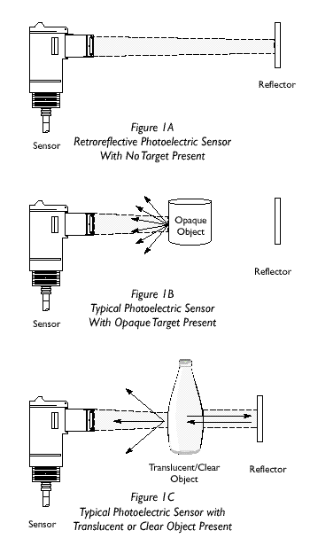
If a "clear object" passes through the above setup (Figure 1C), it will not be detected because the signal passes through the object, bounces off the reflector and returns through the object to the sensor. The result is a very small change in signal. When the light beam from a photoelectric sensor passes through a clear object, scattering and reflection losses reduce its strength by 5% per surface.
If the light beam is polarized, the direction and extent of polarization will be altered to a greater or lesser degree depending on the optical properties of the material. This alteration could depolarize the light beam and reflect a strong detectable signal. Materials that greatly change polarized light are called "optically active." Most plastics used for containers and packaging are optically active. The main use of polarizing filters in photoelectric sensors is to enhance the sensor's ability to ignore reflections from shiny surfaces such as bottles or plastic wrap.
Another characteristic of standard photoelectric sensors is a large 20% to 40% hysteresis level (signal change) that prevents false signals due to noise generated by electromagnetic interference (EMI), radio frequency interference (RFI), and ambient light. This means that when the sensitivity adjustment is turned up enough to energize the output with the reflector in the field of view, a passing object must then reduce the signal by at least 20% (or 40%) to de–energize the output.
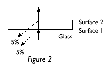
For clear objects, when a light–beam enters perpendicular to a glass surface, approximately 5% of the light energy is lost at each surface (see Figure 2) due to reflection. Two passes through an empty bottle equals eight surfaces for a total light loss of 40%. A single glass plate constitutes two surfaces (Figure 2); two passes through it result in a 20% light loss. It can be seen that a sensor with 20% hysteresis would just barely turn off and back on again with a single glass plate and only if perfectly adjusted.
Practically speaking, this application could not be solved using a sensor with 20% hysteresis because it does not allow for any sensitivity drift or misadjustment. Some clear object detection applications therefore require low hysteresis, typically in the range of 8% to 10%. This would create a more positive "off" condition in the above example. While a sensor with 20% hysteresis would work in an application that sees a 40% light loss, it still only allows for a gain margin buffer of 0.125 above the on- and below the off-thresholds.
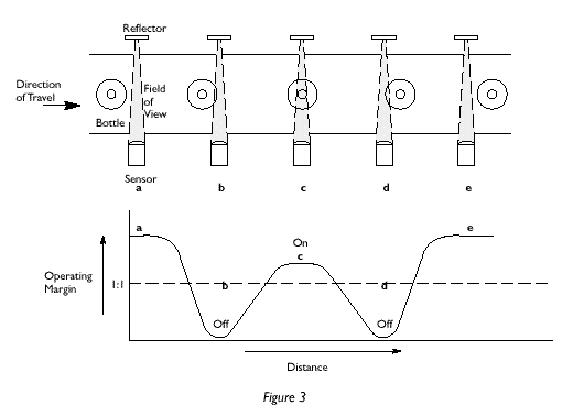
For typical clear bottles, 40% is the theoretical minimum light loss that occurs at the center of the bottle where the surfaces are perpendicular to the light beam. Away from the center, where the bottle surfaces are not perpendicular to the light beam, the light loss due to reflection is greater. This large variation that occurs as the bottle moves through the light beam explains the frequently observed, undesirable "off–on–off" (chatter) sensor performance (Figure 3).
Additionally, clear bottles are not always uniform in their ability to pass light. Certain areas of the bottle may pass the light with a different shift in beam direction than other areas. This lensing effect changes the characteristics of the application, often increasing the signal instead of reducing it. This randomness requires each clear object detection application to be reviewed carefully. All possible orientations and positions (newly molded and "handled" bottles) should be tried to ensure that the clear bottle can be detected reliably.
Testing indicates that new bottles (fresh from the mold) have different optical characteristics from bottles that have been handled by machines or people, even if no scratches or irregular surfaces can be seen on the handled bottles. Therefore it is important to ensure that application test samples include bottles in the condition actually encountered on the production line.
Clear object sensing technology
To accommodate the wide range of optical characteristics seen in industrial applications, clear object detectors use linear polarizers, circular polarizers and coaxial optics.
Linear polarization
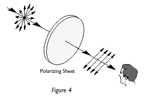
Linear polarization helps reduce primary and specular reflections off a surface. By using a linear polarizer in front of the light source, the light emitted from the sensor is oriented in the direction of the polarizer (Figure 4). Only light waves parallel to the direction of the linear polarizer will be transmitted. When the polarized light bounces off the reflector, the direction of polarization becomes partially random (depolarized). Some of the returned light then passes through a second linear polarizer (positioned perpendicular to the source polarizer) and lands on the photodetector.
When a shiny object blocks the beam, the reflected light remains polarized and does not reach the photodetector because it does not have the same polarity as the filter in front of the detector (Figure 5).
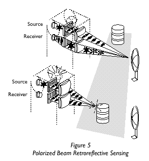
When a clear object is in the beam pattern, part of the light passes through the object while part of the light is reflected off the object back to the sensor. Light that is reflected back to the sensor is effectively blocked. However, when light passes through a plastic material, the properties of the material can cause depolarization of the light. This depolarization could be greater than that achieved by the reflector alone, increasing the light intensity returned to the sensor. Due to this depolarization effect of the material it is particularly difficult to sense plastic items with linearly polarized light. Circular polarized light has been developed to improve detection of clear plastic objects.
Examples of photoelectric sensors with linear polarization are the Allen–Bradley Series 7000 clear object detectors, 42SMU–7250 (NPN output) and 42SMU–7251 (PNP output).
Circular polarization
Circular polarization prevents false signals by requiring the detected light to be polarized only in the direction that the detector can receive (Figure 6). Circular polarizers were initially created to remove ambient light glare from cathode ray tubes. Development and application experience guided the use of circular polarizers in photoelectric applications.
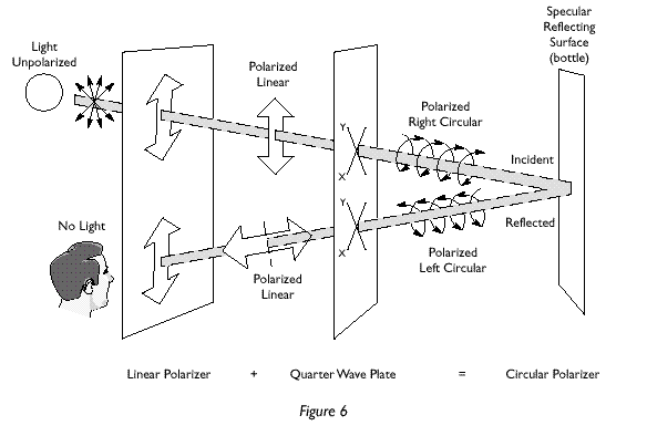
A circular polarizer is a laminate of linear polarizer and a quarter wave plate (see Figure 6). This plate has an optical axis parallel to the flat surface of the polarizer and is oriented at 45° to the linear polarization axis. Nonpolarized light is first linearly polarized; the linearly polarized light has components (x and y) with respect to the quarter wave plate. As the incident light passes through the quarter wave plate, the x and y components emerge 90° out of phase with each other. The polarized light with the x and y components forms a helical pattern from which the name "circular polarized light" is derived.
As this circular polarized light is reflected by a specular reflecting surface (a clear bottle), the circular polarization is reversed. When the light passes back through the quarter wave plate it becomes linearly polarized perpendicular to the linear polarizer. Consequently, the reflected light is blocked.
If the bottle (on the right hand side of Figure 6) is replaced with a reflector, the polarization becomes random after it bounces off the reflector surface. Some of this light passes through the quarter wave plate and the linear polarizer. Consequently, light bounced off of a reflector is not blocked. Circular polarization helps to prevent this "double pulsing" by increasing the difficulty level necessary to depolarize the light.
The Allen–Bradley Series 7000, 42SMU-7260 (NPN output), 42SMU-7261 (PNP output), Series 9000 and Series 10,000 clear object detectors offer circular polarization.
Coaxial optics
Coaxial optics are illustrated in Figure 7, which shows an optical system using a mirror and beam splitter to align the emitter, receiver and circular polarizer along the same optical path. The advantages of coaxial optics over the side–by–side optics used in many transparent object photoelectric sensors available on the market today include:
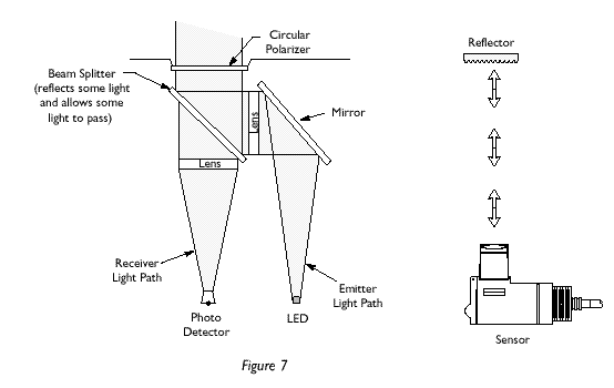
Close Application: When a standard sensor and reflector are very close to each other, the emitted light is reflected directly back to the source, preventing the receiver from viewing any of the transmitted light and creating a blind zone directly in front of the sensor. This is due to the separation of the source and receiver lenses. Coaxial optics significantly reduce the possibility of not coupling the emitted light to the receiver since the source and receiver share the same optical path. Coaxial arrangement allows the user to place the sensor and reflector as close as required without concern of a "dead zone."
Furthermore, some bottles may bend the light in a way that actually increases the coupling of the light source to the receiver and provides higher margin. Therefore, the sensor cannot see the bottle. Bottle variations due to molding and warping (variations in thickness and light transmission can be seen by holding a bottle against the light) are the cause of this effect. In coaxial optics an increase in margin is not possible because the coupling of the light source to the receiver is already maximized.
Narrow Beam and Overlapping Source/Receiver Areas: Coaxial optics provide a narrow light beam that is contained within the receiver field–of–view. With the receiver field–of–view capturing the entire beam, any bending of the light would tend to deflect the beam out of the receiver path. This increases the sensor's ability to see a clear bottle (no returned light means the bottle is seen).
Coaxial optics are used in the Allen–Bradley ClearSight 9000 and ClearSight 10,000 clear object detectors, designed to meet the adverse environmental conditions of bottling operations while providing the discrimination ability to detect clear targets.
Conclusion
The key to reliable clear object detection is extensive application testing. It is important to ensure that application test samples include bottles in the condition actually encountered on the production line. The evaluation of all potential orientations and positions of a target allows a sensor to be chosen based on its effectiveness in dealing with varying optical characteristics.
To accommodate the gamut of optical characteristics possible in an industrial application, clear object detectors use linear polarizers, circular polarizers and coaxial optics. By understanding these technologies and their capabilities, more definitive lines can be drawn regarding the difference between a standard photoelectric sensor application and clear object detection.
For more information: Rockwell Automation, Tel: 414-382-4329, Fax: 414-382-4347, www.rockwellautomation.com
About the Author: Jeffrey R. Holman is marketing manager, photoelectric sensors, for Rockwell Automation Presence Sensing Business (Chelmsford, MA).